Blog / Understanding kV, keV and Efficiency of Kiarmor Bi-layer in Comparison to Lead-free or Composite Materials

Understanding kV, keV and Efficiency of Kiarmor Bi-layer in Comparison to Lead-free or Composite Materials

Understanding kV, keV and Efficiency of Kiarmor Bi-layer in Comparison to Lead-free or Composite Materials

kV is the voltage (Kilovolts = 1000s of volts) across the X-ray lamp that generates the keV (Kilo Electron Volts) spectrum (wavelength bandwidth) of X-ray energy for the main beam.

The keV X-ray spectrum ranges from approximately 15keV to the maximum level of kV used in the X-ray lamp excitation. In other words, if you use 100kV (typical standard X-ray) across the X-ray lamp, the keV spectrum will range from approximately 15keV to 100keV.  If you use 60kV (typical fluoroscope) the keV spectrum will range from approximately 15keV to 60keV

KeV Spectrum 100kV
KeV Spectrum 60kV

Note: The photon count on the Y axis is dependent on current/time selected, so no real scale applied.

Scatter radiation is typically 1% of the main beam. Furthermore, the higher keV energies in the main beam do not scatter as much as they pass through the patient, or object, being X-rayed, whilst the lower energies scatter more easily because they do not have the penetrating power. Therefore, if you look at the resulting keV spectrum for the scatter radiation, the top end of the keV spectrum is reduced.

Typically, if you generated the main beam using 100kV on the lamp, the main beam energy, in terms of keV, will range from approximately 15keV to 100keV (Fig 1), and the scatter radiation will range from approximately 15keV to just over 60keV (Fig 3).

If you generated the main beam using 60kV across the lamp, the main beam energy, in terms of keV, will range from approximately 15keV to 60keV (Fig 2), and the scatter radiation will range from approximately 15keV to just over 45keV (Fig 4).

Scatter Radiation 100kV
Scatter Radiation 60kV

Note: The keV scale of the Y axis (Photon Count) would be approximately a 50th of the graphs for the main beam.

Absorbed dose is created from radiation that does not pass through the body. That is the lower ranges of keV, typically 15keV to approximately 45keV.  Scatter radiation is primarily made up of this range of keV and the core material needs to be at its most efficient and effective in this range to be truly effective in protecting the user.

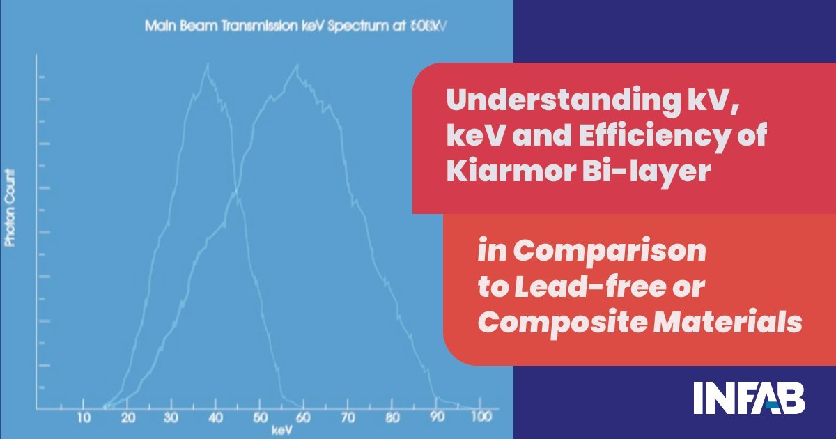
Given the principles above, and taking the example of fluoroscopy, which typically uses between 60kV to 70kV across the lamp to generate the X-rays, the main beam will have keV energies from 15keV to approximately 65keV. However, the scatter radiation will have energies from 15keV to approximately 45keV. This means that the vast majority of the radiation is in the absorbed dose range as it lacks the penetrating power and will stay in the body of the recipient.

Current Lead-free materials use lower-weight atomic elements, for example, Antimony, Tin, Barium, etc., to provide lighter materials that are just able to pass current test standards such as ASTM and IEC 61331-1. However, these elements have K-edges in the critical area of keV in terms of absorbed dose, which is not picked up by the test standards. Higher atomic weight elements, such as Lead or Bismuth, have K-edges beyond the keV spectrum for typical scatter radiation and do not have the same issue.

K-edges create fluorescence and a breakdown of the efficiency of these elements in terms of absorbing photon energy from an X-ray source, or the derived scatter radiation. In fact, these K-edges can actually increase the dose to the wearer of an X-ray protection apron as the fluorescence causes an increase in photon energy to the wearer of an X-ray protection apron made from these lower atomic weight elements (Fig 5). The same applies to materials using a composite (mixture) of a higher and lower atomic weight element, for example, Bismuth/Antimony, or a Lead composite material. That this occurs right next to the wearer is the worst case scenario in terms of protection against absorbed dose.

Scatter Radiation Attenuation

By arranging Lead-free materials as a Bi-layer, with a lower atomic weight element at the top (for example, Antimony) and a higher atomic weight element at the bottom (for example, Bismuth), the K-edge effect is nullified and the additional photons created by the fluorescence of the lower atomic weight element is absorbed by the higher atomic weight element (Fig 6).

Scatter Radiation Attenuation

Independent testing has shown that this Bi-layer configuration is 20% more effective than Lead and 40% more effective than Lead-free materials and composites in terms of absorbed dose. Kiarmor Bi-layer passes all current and future standards, IEC 61331-1, ASTM and DIN 6857-1 (specifically designed for Lead-free materials with geometry and beam conditions designed to capture the K-edge and fluorescence).

October
27, 2021
< Back
Back To Top
Search